OPERATION PRINCIPLE

Solar cookers in today's understanding were started to be developed in 1950s, though many primitive examples are known in history. The idea of a world society that would be influenced from the global environmental problems all together began to appear in the post-war world. One of these environmental problems was deserting, which appeared in arid regions. United Nations and several aid organizations initiated the studies aiming to design solar cookers in order to decrease the dependency on plant cover for fuel. The outcomes of these studies were that the appropriately set up solar cookers were highly suitable for preparation of food and they were even easy mechanisms to set up and use.

Open reflector type solar cookers used in our project provide the energy to cook by focusing the solar rays on the pots placed in the center. A solar cooker designed in optimum dimensions can be used for cooking whatever put on it, as the conventional cookers. Larger the reflector surface, higher the energy collected and shorter the cooking time; however, increasing the dimensions makes the cooker difficult to move, adjust and carry.


Cooker Plan (pdf): 1 2 3 4


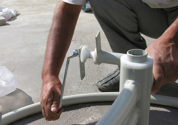
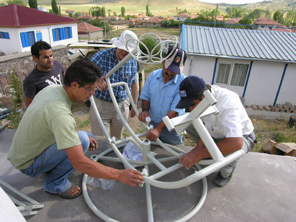
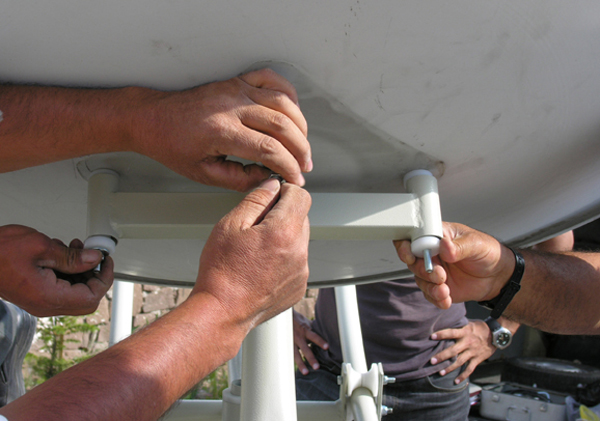
Firstly the polyamide constellation to which the curved support would be attached, subsequently the rollers that maintained the movement were attached to the legs that fixed the cooker to the ground.


The curved support, which would maintain the movement of the calyx with respect to the angle of the solar rays, was placed on the rollers. Attached to the legs were the frame and the basket, which would carry the pot regardless of the movement of the calyx.


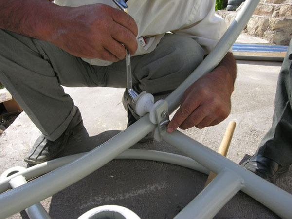
2nd rollers were put on the curved support and were screwed to the lower rollers so that the movement line of the axis was fixed.


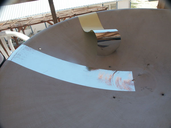
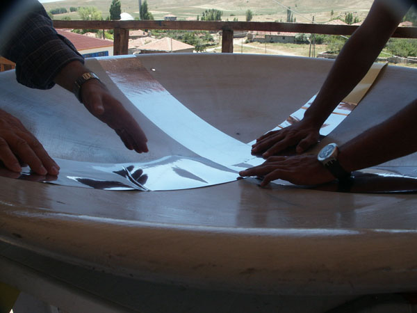
Concave surface of the calyx was covered with aluminium, which would reflect the solar radiation to the center.


Aluminium cut in 15 cm wide strips for covering the surface of the calyx was pasted vertically to each others from the center to the periphery in a way not to leave any empty space on calyx.


The calyx was screwed to the foursome leg, which was attached to the curved support.